The hierarchy of geometric constructibility: can we go back?

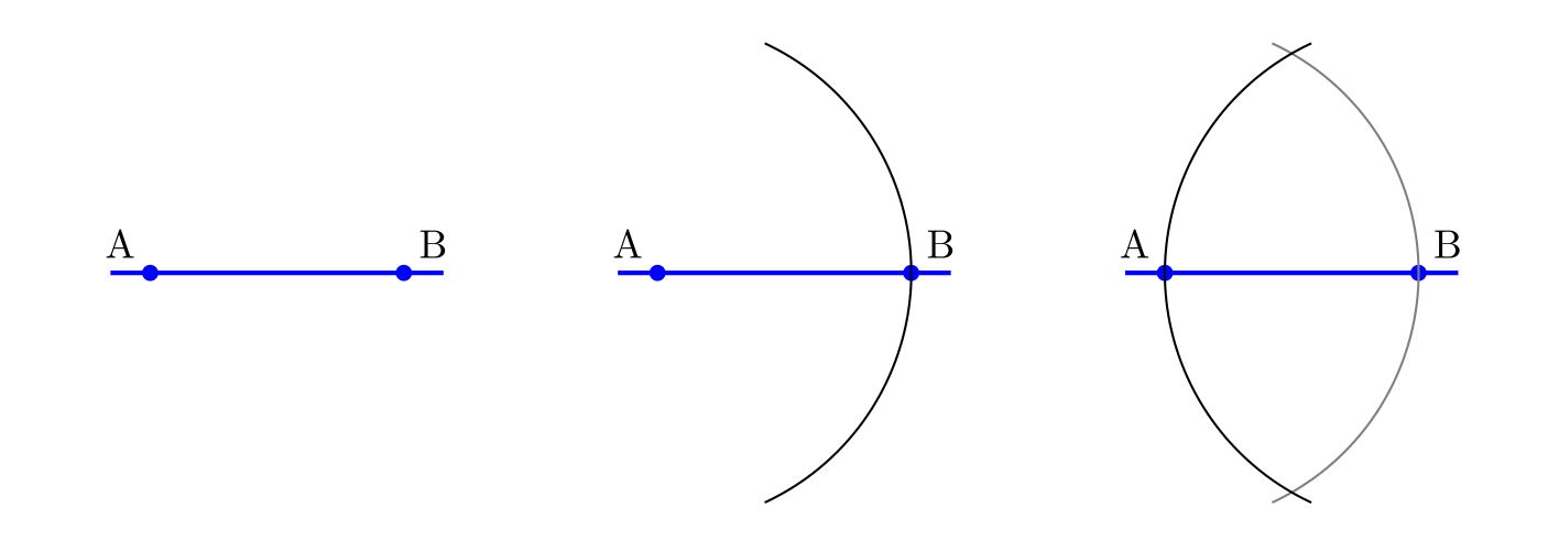
I have recently become interested in the hierarchy of relative constructibility in geometry (see the discussion on my Twitter thread). From a given collection of points in the plane, we may proceed to construct other points using the classical tools of straightedge and compass. This induces a hierarchy of relative constructiblity, namely, for any two sets of points $X$ and $Y$ in the plane, we may say that $X$ is constructible from $Y$, written as $$X\trianglelefteq Y$$ if for every point $A\in X$, there is a construction procedure using only straightedge and compass proceeding from points in $Y$ and constructing $A$. And so we are faced with a hierarchy of constructibility.

Perhaps one might ask immediately whether this is genuinely a hierarchy. A central case occurs with pairs of points, since one often proceeds in geometry with the idea of a unit segment having already been fixed.

Question 1. Given two distinct points A and B, suppose that distinct points C and D are constructible by straightedge and compass. Can we go back? That is, must A and B both be constructible from C and D?

The answer, surprisingly, is Yes! This is a sense in which the relative constructibility notion is an equivalence relation rather than a hierarchy, since it shows that if AB can construct CD, than it is also true conversely. Since constructibility is also transitive, this shows that the relative constructibility is an equivalence relation on pairs of points in the plane.

Before addressing the question, let me first dispense with a distracting line of reasoning that suggests a wrong answer to this question. Suppose that we have a segment AB of length $\sqrt[3]2$, a nonconstructible number. Since the constructible numbers are closed under multiplication, this might suggest that from AB we can construct a segment of length 2, and therefore also construct a segment CD of length 1. But from a segment of length 1, we can never construct a segment of length $\sqrt[3]2$, because the duplication of the cube is impossible. So this would suggest a negative answer to the question. Is it right?

But no, this distracting counter-argument is not correct. The reason is that although the constructible numbers are indeed closed under multiplication, the construction methods requires the consultation of a fixed unit segment. That is, to prove that from a segment of length $a$ and a segment of length $b$ one can construct a segment of length $ab$, we require the use of fixed unit segment of length $1$. Indeed, it will follow from our analysis here that one cannot omit this consultation of a unit segment from the construction—we cannot in general construct the cube of a segment just from the segment itself.

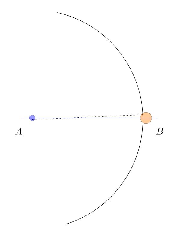
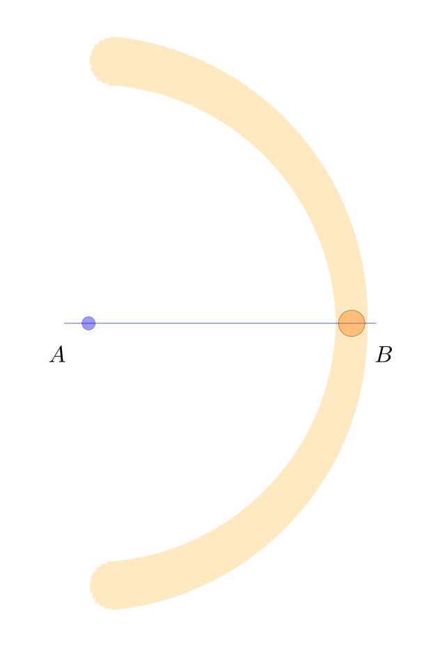
So let me prove the answer to question 1 is positive. Suppose that from distinct points AB we can construct distinct points CD. Performing excactly the same construction process again, but proceeding from points CD as input, we construct points EF. From points CD we can see how CD are related to EF, forming a quadrilateral CDFE.

The point is that we may now construct the points A and B from C and D by simply inverting this similarity. (This was also observed by user @ZenoRogue on Twitter.) Namely, the two quadrilaterals ABDC and CDFE are similar, and so have all the same angles. So the line AC is constructible from CD by the angle ACD, which is the same as CEF, and the distance AC is scaled from CE by the same factor that CD is related to EF. So from CD we can construct this similar quadrilateral, and thereby construct both A and B.

Question 2. Given three distinct points forming a triangle ABC, suppose that we can construct triangle DEF by straightedge and compass. Can we go back? That is, must A,B, and C be constructible from D,E,F?

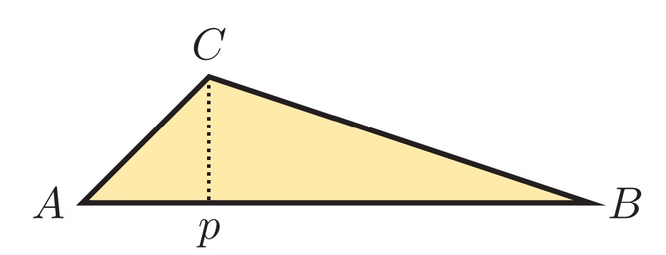
The question is of course similar to question 1, which had a positive answer. Nevertheless, the answer here is negative. The reason is that the original idea we had with question 1 concerning $\sqrt[3]2$ now works here to refute question 2. Namely, let ABC be a right triangle where AB has length 1 but AC has length $\sqrt[3]2$.

From the triangle ABC, we may easily construct the triangle ABD, where AD has length 1, since in fact the point D is constructible from the segment AB alone. But from ABD, which is a right triangle with both legs of length 1, we shall be unable to construct the number $\sqrt[3]2$, and consequently unable to construct the point C. So although ABD is constructible from ABC, the point C is not constructible from points ABD. This is therefore a counterexample to question 2, which therefore must be answered in the negative.

Another argument, offered by Ed Wagstaff, is that from an angle trisection we can construct the original angle, but we can’t necessarily construct the trisection from the original angle.

Finally, I should like to understand the nature of the relative hierarchy of constructibility better. $$X\trianglelefteq Y$$ What is the nature of relative constructibility of sets of points in the plane? For example, one question I didn’t know how to answer at first is the following:

Question 3. Is the hierarchy of relative constructibility a dense order? That is, if the set $X$ is constructible from $Y$ but not conversely, must there be a set of points $Z$ strictly in between? $$X\lhd Y\quad\implies\quad\exists Z\quad X\lhd Z\lhd Y?$$

In an exchange on Twitter with David Madore, I had thought that we answered the question negatively, but now I am not at all sure of that argument (and thanks to Gabin for the comments below!), and so I have deleted the wrong argument here. Question 3 seems currently to be open.

I have now asked question 3 on MathOverflow: Is the hierarchy of relative geometric constructibility by straightedge and compass a dense order?

The propagation of error in classical geometry constructions

I’d like to discuss the issue of error and error propagation in the constructions of classical geometry. How does error propagate in these constructions? How sensitive are the familiar classical constructions to small errors in the use of the straightedge or compass?

Let me illustrate what I have in mind by considering the classical construction of Apollonius of the perpendicular bisector of a line segment $AB$.  One forms two circles, centered at $A$ and $B$ respectively, each with radius $AB$. These arcs intersect at points $P$ and $Q$, respectively, which form the perpendicular bisector, meeting the original segment at the midpoint $C$.

That is all fine and good, and one can easily prove that indeed $PQ$ is perpendicular to $AB$ and that $C$ is the midpoint of $AB$, as desired.

When carrying out such a construction in practice, however, there will inevitably be some small errors. We do not expect to implement it exactly, with infinite precision, but rather, we expect some small errors in the placement of the compass or straightedge, and perhaps these errors may accumulate and they propagate through the construction. What I would like to discuss is the sensitivity of this construction and the other classical constructions to these small errors.

For example, suppose that we are given points $A$ and $B$. When we seek to construct the circle centered at $A$ with radius $AB$, we place the point of the compass at $A$, and this placement may have some small error deviating from $A$, landing somewhere in the blue circle. Similarly, the writing (or etching) implement end of the compass is placed at $B$, with its own possibly different error, landing the orange circle at $B$. The arc actually resulting will be some arc arising with some such small errors, like this:

We may represent the space of all arcs that could arise in conformance with those error bounds as the blurred orange arc below. This image was created simply by drawing many dozens of such arcs in orange, with various choices for the center and radius within the error circles, and blending the results together.

We carry out the same construction with similar errors for the other arc, centered at $B$ and passing through $A$. These arcs overlap in the darker orange regions above and below, determining the points $P$ and $Q$.

The actual arcs we draw and the corresponding vertical will land somewhere inside these blurred regions, perhaps like this:

Note that in this particular case, the resulting line $PQ$ is noticably non-perpendicular to $AB$, and the resulting point $C$ is noticably not the midpoint. Consider the space of all the bisectors $PQ$ that might arise in conformance with our errors on $A$ and $B$, showing the result as the vertical red shaded region.   The darker red region is the space of possible points $C$ that we might have constructed as the “midpoint” $C$, in conformance with the error estimates.

Given the size of the original error bounds on the points $A$ and $B$, it may be surprising that even such a standard simple construction as this — constructing the perpendicular bisector and midpoint of a segment — appears to have comparatively large error propagation, since the shaded red region $C$ is quite large and includes many points that one would not say are close to being the midpoint.  In this sense, the Apollonius perpendicular bisector construction appears to be sensitive to the errors of compass placement.

Is there a better construction? For example, in terms of improving the accuracy at least of the perpendicularity of $PQ$ to $AB$, it would seem to help to use a much larger circle, which would lower the variation in the resulting “right” angle.  But this is partly because we have so far assumed that compass error arises only with the placement of the points of the compass, and not during the course of actually drawing the arc. But of course, one can imagine that errors arise from a flexing of the compass during use, causing it to deviate from circularity, or from slippage, which might reasonably be expected to cause increasing error with the length or degree of the arc, and so on, and such a model of error might have greater errors with large circles.

One could in principle carry out similar analyses for any geometric construction, and use the corresponding results to compare the sensitivity of various methods for constructing the same object, as well as modeling different sources of error.  The goal might be to mount a precise analysis of all the standard constructions and compare competing constructions for accuracy.

There is a literature of papers doing precisely this, and I will try to post some references later (or please do so in the comments, if you have some good ones).

Another approach to error estimation would be to think of the errors at points $A$ and $B$ as probability distributions, centered at $A$ and $B$ and with a certain variation; and one then gets corresponding distributions for the points $P$ and $Q$, which are not rigid shapes as in my diagrams, but qualitatively similar distributions spread out in that region, and a resulting probability distribution for the point $C$.

Finally, let me mention that one might hope to improve the accuracy of a construction, simply by repeating it and averaging the result, or by some other convergence algorithm. For example, as a first step, we might simply perform the Apollonius bisector construction twice, producing midpoint candidates $C_0$ and $C_1$, and we could proceed simply find the midpoint of $C_0C_1$ as a further presumably more accurate midpoint. Or we could iterate in some other manner and hope to converge to the actual midpoint. For example, we could produce seven midpoint candidates, and take the resulting median point.

Draw an infinite chessboard in perspective, using straightedge only

I’d like to explain to you how to draw chessboards by hand in perfect perspective, using only a straightedge.  In this post, I’ll explain how to construct chessboards of any size, starting with the size of the basic unit square.

This post follows up on the post I made yesterday about how to draw a chessboard in perspective view, using only a straightedge.  That method was a subdivision method, where one starts with the boundary of the desired board, and then subdivides to make a chessboard. Now, we start with the basic square and build up. This method is actually quite efficient for quickly making very large boards in perspective view.

I want to emphasize that this is something that you can actually do, right now. It’s fun! All you need is a piece of paper, a pencil and a straightedge. I’ll wait right here while you gather your materials. Use a ruler or a chop stick (as I did) or the edge of a notebook or the lid of a box. Sit at your table and draw a huge chessboard in perspective. You can totally do this.

Start with a horizon, having two points at infinity (orange), at left and right, and a third point midway between them (brown), which we will call the diagonal infinity. Also, mark the front corner of your chess board (blue).

Extend the front corner to the points at infinity. And then mark off (red) a point that will be a measure of the grid spacing in the chessboard. This will the be size of the front square.

You can extend that point to infinity at the right. This delimits the first rank of the chessboard.

Next, extend the front corner of the board to the diagonal infinity.

The intersection of that diagonal with the previous line determines a point, which when extended to infinity at the left, produces the first square of the chessboard.

And that line determines a new point on the leading rank edge. Extend that point up to the diagonal infinity, which determines another point on the second rank line.


Extend that line to infinity at the left, which determines another point on the leading rank edge.

Continuing in this way, one can produce as many first rank squares as desired. Go ahead and do that. At each step, you extend up to the diagonal infinity, which determines a new point, which when extended to infinity at the left determines another point, and so on.

If you should now reflect on the current diagram, you may notice that we have actually determined many further points in the grid than we have mentioned — and thanks to my daughter Hypatia for noticing this simplification — for there is a whole triangle of further intersection points between the files and the diagonals.

We can use these points (and we do not need them all) to construct the rest of the board, by drawing out the lines to infinity at the right. Thus, we construct the whole chessboard:

One can construct a perspective chessboard of any size this way, and one can simply continue with the construction and make it larger, if desired.

It will look a little better if you add a point at infinity down below (and do so directly below the diagonal point at infinity, but a good distance down below the board), and extend the board downward one level. The corresponding diagram on yesterday’s post might be helpful.


You can now color the tile pattern, and you’ll have a chessboard in perfect perspective view.


If you keep going, you can make extremely large chessboards. In time, I hope that you will come to learn how to complete an infinite chess board in finite time.


Draw a chessboard in perspective view, using straightedge only

Let me show you how to hand-draw an image of a chessboard in perspective, using only a straightedge. There is no need to measure any distances or to make calculations of any kind.  All you need is a straightedge, paper and your pen or pencil.

Imagine the vast doodling potential!  A person who happens to be stuck in a lecture on some other less interesting topic could easily make one or more elaborate chessboards in perfect perspective, using only a straightedge! Please carry out the construction and then share your resulting images. I would love to see them.

To begin, give yourself a horizon at the top of the page, with two points at infinity (in orange), and also two points (blue) that will become the front and back corner of your chessboard.  You can play around with different arrangements of these points, which will lead ultimately to different perspective views.

Using your straightedge, draw the lines from those reference points to the points at infinity. The resulting enclosed region will ultimately become the main chess board. One can alternatively think of starting with the front edges of the desired board, and then setting a horizon and using that to determine the points at infinity, and then adding the back edges. If you like, you can add a third point at infinity down below, and a front bottom reference point (blue), to give the board some thickness. Construct the lines to the bottom point at infinity.

The result is now the main outline of your chessboard as a rectangular solid.

Next, construct the center point of the top face, by drawing the two diagonals and finding the intersection point. I call this the center point, because it is the point that represents in the perspective view the actual center point of the chessboard, even though this point is not in the “center” of the quadrilateral representing the board. It is remarkable that one can find that point without needing to measure or calculate anything, simply because the two straight lines of the diagonal of the chessboard intersect at that point, and this remains true in the perspective view. This is the key idea that enables the entire construction method to proceed with only a straightedge.

Construct the midpoint lines by drawing the lines from that centerpoint to the points at infinity.

Now you have the chessboard with the main midlines drawn.

Construct the center points of the two diagonal squares, by intersecting the diagonals of each of them.

Construct the lines that extend those points to the points at infinity.

Thus, you have constructed the main 4 x 4 grid.

You can extend the grid lines down to the bottom point at infinity like so:

One can stop with the 4 x 4 board, if desired. Simply add suitable shading, and you’ve completed the 4 x 4 chessboard in perspective.

Alternatively, one can continue with one more iteration to construct the 8 x 8 board. From the 4 x 4 grid (with no shading yet) simply construct the center points of the squares on the main diagonal, and extend those lines to infinity.  This will enable you to draw the 8 x 8 grid lines, and after shading, you’ll have the complete chessboard.

The initial arrangement of points affects the nature of the perspective view. Having the points at infinity very far away will produce something closer to orthoprojection; having them close produces a more extreme perspective, which simulates a view from a vantage point extremely close to the board.

Please give the construction a try! All you need is paper, pencil and a straightedge! Provide links below in the comments to photos of your creations.

Meanwhile, let me point you towards my follow post, How to draw infinite chessboards by hand in perfect perspective, using only a straightedge. The difference between the methods is that the method of this post is about subdividing a given board, and the other method is about generating arbitrarily large chessboards from a given unit square.

I learned these construction method years ago from my CUNY geometer colleague Ilya Kofman.

All triangles are isosceles

Let me share a mathematical gem with you, the following paradoxical “theorem.”

Theorem. Every triangle is isosceles.

Proof. Consider an arbitrary triangle $\triangle ABC$. Let $Q$ be the intersection of the angle bisector (blue) at $\angle A$ and the perpendicular bisector (green) of $BC$ at midpoint $P$.

Isosceles triangle

Drop perpendiculars from $Q$ to $AB$ at $R$ and to $AC$ at $S$. Because $P$ is the midpoint of $BC$ and $PQ$ is perpendicular, we deduce $BQ\cong CQ$ by the Pythagorean theorem. Since $AQ$ is the angle bisector of $\angle A$, the triangles $AQR$ and $AQS$ are similar, and since they share a hypotenuse, they are congruent. It follows that $AR\cong AS$ and also $QR\cong QS$. Therefore $\triangle BQR$ is congruent to $\triangle CQS$ by the hypotenuse-leg congruence theorem. So $RB\cong SC$. And therefore,
$$AB\cong AR+RB\cong AS+SC\cong AC,$$
and so the triangle is isosceles, as desired. QED

Corollary.  Every triangle is equilateral.

Proof. The previous argument proceeded from an arbitrary vertex of the triangle, and so any pair of adjacent sides in the triangle are congruent. So all three are congruent, and therefore it is equilateral. QED

Perhaps you object to my figure, because depending on the triangle, perhaps the angle bisector of $A$ passes on the other side of the midpoint $P$ of $BC$, which would make the point $Q$ lie outside the triangle, as in the following figure.

Isosceles triangle 2

Nevertheless, essentially the same argument works also in this case. Namely, we again let $Q$ be the intersection of the angle bisector at $\angle A$ with the perpendicular bisector of $BC$ at midpoint $P$, and again drop the perpendiculars from $Q$ to $R$ and $S$. Again, we get $BQ\cong CQ$ by the Pythagorean theorem, using the green triangles. And again, we get $\triangle ARQ\cong\triangle ASQ$ since these are similar triangles with the same hypotenuse. So again, we conclude $\triangle BQR\cong\triangle CQS$ by hypotenuse-leg. So we deduce $AB\cong AR-BR\cong AS-CS\cong AC$, by subtracting rather than adding as before, and so the triangle is isosceles.

Question. What is wrong with these arguments?

Please post your answers in the comments below.

The argument is evidently due to W. W. Rouse Ball, Mathematical Recreations and Essays (1892). I first heard it years ago, when I was in graduate school.  Shortly afterward, my advisor W. Hugh Woodin happened to be a little late to seminar, and so I leaped to the chalkboard and gave this proof, leaving the distinguished audience, including R. Solovay, scratching their heads for a while. Woodin arrived, but Solovay wouldn’t let him start the seminar, since he wanted to resolve the triangle argument. What fun!

My very first lemma, which also happened to involve a philosophical dispute

Doppelverh-zentralproj.svgLet me recall the time of my very first lemma, which also happened to involve a philosophical dispute.

It was about 35 years ago; I was a kid in ninth grade at McKinley Junior High School, taking a class in geometry, taught by a charismatic math teacher. We were learning how to do proofs, which in that class always consisted of a numbered list of geometrical assertions, with a specific reason given for each assertion, either stating that it was “given” or that it followed from previous assertions by a theorem that we had come to know. Only certain types of reasons were allowed.

My instructor habitually used the overhead projector, writing on a kind of infinite scroll of transparency film, which he could wind up on one end of the projector, so as never to run out of room. During the semester, he had filled enough spools, it seemed, to fill the library of Alexandria.

One day, it came to be my turn to present to the rest of the class my proof of a certain geometrical theorem I had been assigned. I took the black marker and drew out my diagram and theorem statement. In my proof, I had found it convenient to first establish a certain critical fact, that two particular line segments in my diagram were congruent $\vec{PQ}\cong\vec{RS}$. In order to do so, I had added various construction lines to my diagram and reasoned with side-angle-side and so on.

Having established the congruency, I had then wanted to continue with my proof of the theorem. Since the previous construction lines were cluttering up my diagram, however, I simply erased them, leaving only my original diagram.

The class erupted with objection!  How could I sensibly continue now with my proof, claiming that $\vec{PQ}\cong\vec{RS}$, after I had erased the construction lines? After all, are those lines segments still congruent once we erase the construction lines that provided the reason we first knew this to be true? Many of the students believed that my having erased the construction lines invalidated my proof.

So there I was, in a ninth-grade math class, making a philosophical argument to my fellow students that the truth of the congruence $\vec{PQ}\cong\vec{RS}$ was independent of my having drawn the construction lines, and that we could rely on the truth of that fact later on in my proof, even if I were to erase those construction lines.

After coming to an uneasy, tentative resolution of this philosophical dispute, I was then allowed to continue with the rest of my proof, establishing the main theorem.

I realized only much later that this had been my very first lemma, since I had isolated a mathematically central fact about a certain situation, proving it with a separate argument, and then I had used that fact in the course of proving a more general theorem.